

Introduction: Why Multimeter Symbols Trip Everyone Up
You grab your multimeter, ready to test a circuit. Then you freeze. The dial is covered in tiny symbols — squiggly lines, capital letters, dashes, Greek letters — and you’re not sure which one to turn to.
Sound familiar?
You’re not alone. Even experienced hobbyists and DIYers occasionally second-guess what each symbol means, especially when switching between AC voltage, DC voltage, resistance, and current measurements.
This guide breaks down every major symbol you’ll find on a multimeter or voltmeter — starting with the all-important AC voltage symbol — in plain English. No electrical engineering degree required.
By the time you’re done reading, you’ll know exactly what you’re looking at, what each setting does, and how to use your meter confidently and safely.
What Is the AC Voltage Symbol?
The AC voltage symbol is one of the most commonly searched electrical terms — and for good reason. Alternating current (AC) is what powers your home outlets, appliances, and most of the electrical grid.
On a multimeter, the symbol for AC voltage appears in a few different forms:
- ~ (tilde) — the most universal AC symbol
- VAC — Volts Alternating Current
- ACV — Alternating Current Volts (some older meters)
- A sine wave or squiggly line (~) next to a V
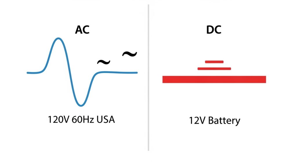
The tilde (~) is the international shorthand for alternating current because AC power oscillates back and forth — like a wave — rather than flowing in one constant direction.
In the United States, standard household AC voltage runs at 120V at 60 Hz, meaning the current alternates direction 60 times per second. In most of Europe, it’s 230V at 50 Hz. When your multimeter is set to AC voltage mode, it measures this oscillating voltage.
Expert Tip: Always set your multimeter to a range higher than the voltage you expect to measure. If you’re testing a 120V US outlet, set it to 200V AC or higher — never lower. Many modern meters are auto-ranging and do this automatically.
The Complete List of Multimeter Symbols and Their Meanings
Let’s go through every symbol you’re likely to encounter. This is your master reference for multimeter symbols and meanings.
Voltage Symbols on a Multimeter
AC Voltage (V~)
- Symbol: V~ or ACV or VAC
- What it measures: Alternating current voltage (wall outlets, appliances, generators)
- Typical ranges: 200V, 600V, 750V (or auto-range)
- Use case: Testing if a wall outlet has power, measuring generator output
The tilde (~) is always your signal for AC. If you see V~ on the dial, that’s where you put it to test AC circuits.
DC Voltage (V— or VDC)
- Symbol: V— (V with a solid line and dashed line below) or VDC
- What it measures: Direct current voltage (batteries, car circuits, solar panels)
- Typical ranges: 200mV, 2V, 20V, 200V, 600V
- Use case: Testing a car battery, measuring USB power output
The symbol for DC voltage uses a solid line (—) and a dashed line below it (- – -). This represents the constant, one-directional flow of DC electricity — think of it as a flat, steady river versus AC’s ocean waves.
Symbol for DC volts quick reference:
V—orVDCor sometimes justDC V
Millivolt (mV)
- Symbol: mV~ or mV—
- What it measures: Very small voltages (1 millivolt = 0.001 volts)
- Use case: Measuring small sensor outputs, thermocouple voltages
The millivolt symbol is simply a lowercase “m” before the V. Useful in precision electronics work.
Current (Amperage) Symbols on a Multimeter
Current is the flow of electricity — measured in amps (A). Here’s how the amp symbol on a multimeter breaks down:
AC Amps (A~)
- Symbol: A~
- What it measures: Alternating current flow
- Use case: Measuring current draw of an AC appliance
DC Amps (A—)
- Symbol: A— or DCA
- What it measures: Direct current flow
- Use case: Measuring battery drain, car electronics current draw
The DC current symbol on a multimeter follows the same solid-line/dashed-line convention as DC voltage — it just has an “A” instead of a “V.”
Milliamps (mA)
- Symbol: mA
- What it measures: Thousandths of an amp
- Use case: Measuring current in small circuits, LED drivers
The symbol for milliamps (mA) is critical for low-power electronics. One milliamp = 0.001 amps.
Milliamps symbol note: Some meters have separate mA and A terminals on the physical meter — always check which input jack you’re using, not just the dial setting.
Microamps (μA)
- Symbol: μA
- What it measures: Millionths of an amp
- Use case: Measuring ultra-low-power sensor currents
The microamps symbol uses the Greek letter mu (μ). This is used for extremely sensitive current measurements, common in medical devices and precision instruments.
Amps Symbol Summary Table
| Symbol | Full Name | Equals | Common Use |
|---|---|---|---|
| A~ | AC Amps | Full amperage (AC) | Appliances, HVAC |
| A— | DC Amps | Full amperage (DC) | Batteries, car circuits |
| mA | Milliamps | 0.001 A | Small electronics |
| μA | Microamps | 0.000001 A | Precision sensors |
Resistance Symbol on Multimeter (Ohms — Ω)
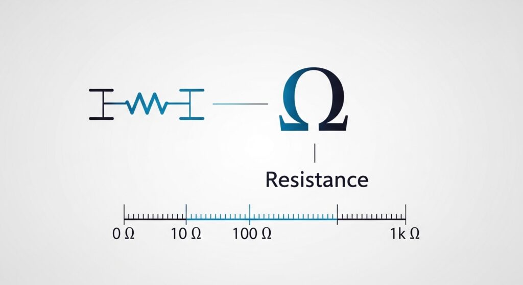
- Symbol: Ω (Greek letter Omega)
- What it measures: Electrical resistance in ohms
- Typical ranges: 200Ω, 2kΩ, 20kΩ, 200kΩ, 2MΩ, 20MΩ
- Use case: Testing resistors, checking wire continuity, diagnosing shorts
The multimeter ohms symbol is the Greek capital letter Omega (Ω). Resistance tells you how much a component opposes the flow of electricity.
- kΩ = kilohms (1,000 ohms)
- MΩ = megaohms (1,000,000 ohms)
- Mega ohms symbol: MΩ — used for insulation testing and high-resistance measurements
Ohmmeter symbol note: Some meters label the resistance mode as simply “OHM” or show just the Ω with range indicators. Never measure resistance on a live circuit — always de-energize first.
Continuity Test Symbol
- Symbol: A diode symbol + sound waves, or just a speaker/wave icon
- What it does: Beeps when there’s a complete electrical path (< ~50Ω typically)
- Use case: Checking if a wire is broken, testing fuses, verifying connections
The multimeter continuity test symbol looks like a diode arrow pointing right, often paired with a small dot or sound-wave lines. When you touch two connected points, the meter beeps — a quick audible confirmation without reading numbers.
This is one of the most-used features by electricians and hobbyists. No beep? The circuit is open (broken). Beep? You’ve got continuity.
Diode Test Symbol
- Symbol: A triangle pointing right with a vertical bar (→|)
- What it does: Tests if a diode is functioning properly
- Use case: Checking if a diode allows current in one direction only
Frequency Symbol (Hz)
- Symbol: Hz
- What it measures: Frequency of AC signals in Hertz
- Use case: Verifying power line frequency (60 Hz in the US), testing signal generators
Temperature Symbol (°C / °F)
- Symbol: °C or °F (with thermocouple input)
- What it measures: Temperature via a Type-K thermocouple probe
- Use case: HVAC diagnostics, checking motor heat, food safety
Capacitance Symbol (F / μF / nF)
- Symbol: F, μF, or nF
- What it measures: Capacitance of capacitors
- Use case: Testing if a capacitor is working, checking capacitor values
AC vs. DC Symbol: Understanding the Difference
One of the most common points of confusion is DC vs AC symbol identification. Here’s the clearest breakdown:
| Feature | AC (Alternating Current) | DC (Direct Current) |
|---|---|---|
| Symbol | ~ (tilde) or sine wave | — (solid line + dashes) |
| Multimeter setting | V~ or ACV | V— or VDC |
| Waveform | Oscillates back and forth | Flows in one direction |
| Common sources | Wall outlets, generators | Batteries, solar panels, USB |
| US standard | 120V / 60Hz | Varies (1.5V–48V typical) |
The AC DC current symbol difference is simple once you know it: AC uses wavy lines (~), DC uses straight lines (—).
Symbols on a Voltmeter: Are They Different from a Multimeter?
A voltmeter is a specialized tool that only measures voltage. A multimeter measures voltage, current, resistance, and more. But their voltage symbols are identical:
- Symbol for AC volts on a voltmeter: V~ or VAC
- Symbol for DC volts on a voltmeter: V— or VDC
The symbols on a voltmeter mirror what you’d see on the voltage section of a multimeter dial. If you’re using a dedicated volt meter, the display or dial will still use the same tilde (~) for AC and solid/dashed lines (—) for DC.
Voltmeter symbol meaning: The key difference is that voltmeters have high internal resistance (typically 10MΩ) to avoid affecting the circuit being measured. This is why the symbol for a voltmeter in circuit diagrams shows a circle with a “V” — representing a high-impedance measuring device.
What Do the Symbols on a Multimeter Mean? (Full Quick Reference)
Here’s a consolidated reference table — your one-stop answer to “what do multimeter symbols mean?”
| Symbol | Name | Meaning |
|---|---|---|
| V~ | AC Volts | Alternating current voltage measurement |
| V— | DC Volts | Direct current voltage measurement |
| A~ | AC Amps | Alternating current measurement |
| A— | DC Amps | Direct current measurement |
| mA | Milliamps | 1/1,000 of an amp |
| μA | Microamps | 1/1,000,000 of an amp |
| Ω | Ohms | Resistance measurement |
| kΩ | Kilohms | 1,000 ohms |
| MΩ | Megaohms | 1,000,000 ohms |
| →| | Diode | Tests diode function |
| ))) or wave | Continuity | Tests for complete circuit path |
| Hz | Hertz | Frequency measurement |
| °C / °F | Temperature | Thermocouple temperature |
| F / μF | Capacitance | Capacitor value testing |
| hFE | Transistor gain | BJT transistor testing |
| % | Duty Cycle | PWM signal analysis |
Multimeter Functions Explained
Understanding the symbols is only half the battle. Here’s how the main multimeter functions work in practice:
Measuring AC Voltage
- Set the dial to V~ (AC Volts)
- If not auto-ranging, select a range higher than expected voltage (e.g., 200V for a US outlet)
- Insert red probe into VΩmA jack, black probe into COM jack
- Touch red probe to hot terminal, black to neutral or ground
- Read the display — expect ~120V for a US outlet
Measuring DC Voltage
- Set dial to V— (DC Volts)
- Select appropriate range or use auto-range
- Same probe setup as above
- Touch red to positive terminal, black to negative
- A 9V battery should read approximately 9V DC
Measuring Resistance
- De-energize the circuit completely
- Set dial to Ω
- Touch probes to both ends of the component
- Read the display in ohms, kilohms, or megaohms
Testing Continuity
- Set to continuity mode (the beep/wave symbol)
- Touch probes to both ends of a wire or fuse
- Beep = good connection. Silence = open circuit
Measuring Current (Amps)
- Set to A~ or A— depending on circuit type
- Important: Move red probe to the dedicated 10A input jack if measuring high current
- Current must be measured in series (the meter must be part of the circuit path)
Safety Warning: Never measure current in parallel or attempt to measure AC voltage while in current mode. This can destroy your meter or cause injury. Always double-check your dial setting before touching probes to a live circuit.
Voltage Tester Symbols vs. Multimeter Symbols
A non-contact voltage tester (NCV tester) is simpler than a multimeter — it just beeps or lights up near live AC voltage. These tools typically only use a few symbols:
- AC wave symbol (~): The tester is set for AC detection
- V or VAC: Indicates voltage detection mode
- LED/light indicator: Visual alert for live voltage
These voltage tester symbols are more limited than full multimeter symbols but serve a critical safety function — especially for electricians quickly checking if a wire is live before touching it.
Expert Tips for Reading Multimeter Symbols Accurately
After years of working with meters, here are the practical tips that make a real difference:
1. Learn the two master symbols first
Master AC (~) and DC (—) before anything else. Every voltage and current measurement flows from this distinction.
2. Auto-range saves mistakes
If your meter offers auto-ranging (usually labeled “AUTO” on the display), use it. It selects the right measurement range automatically, preventing the dreaded “OL” (overload) reading.
3. The COM jack is always black
Your black probe always goes in the COM (Common/Ground) jack. The red probe moves between VΩmA and 10A depending on what you’re measuring.
4. Never measure resistance in a live circuit
The Ω setting applies a small test current. If there’s existing voltage in the circuit, you’ll get a wrong reading at best — and damage your meter at worst.
5. For amps, you need the right jack
Small currents (under 200mA–400mA) use the VΩmA jack. Large currents use the dedicated 10A or 20A jack. Wrong jack = blown fuse inside your meter.
6. Fluke, Klein, and UNI-T share common symbols
Brands like Fluke, Klein Tools, and UNI-T all follow IEC 61010 safety standards for meter symbols — so once you learn the symbols on one quality meter, they transfer to others.
7. Check the CAT rating
Multimeters display CAT II, CAT III, or CAT IV safety ratings. Higher CAT numbers = safer for higher-energy environments. Fluke’s guide to CAT ratings explains this well.
Common Multimeter Symbol Mistakes (and How to Avoid Them)
Mistake 1: Confusing V~ and V—
Measuring DC voltage (battery) with the AC setting — or vice versa — gives you a wrong or zero reading. Double-check: tilde (~) for AC, dashes (—) for DC.
Mistake 2: Leaving the Probe in the 10A Jack
After measuring high current, forgetting to move the probe back to VΩmA before measuring voltage can blow the 10A fuse — or worse, create a short circuit. Always check your probe placement.
Mistake 3: Ignoring Polarity on DC
DC measurements are polarity-sensitive. Red = positive, black = negative. Reversed probes on a DC circuit show a negative reading (which is fine for the meter) but can cause confusion.
Mistake 4: Setting to mA When You Need A
If you’re measuring high current (like a car’s starter motor draw), using the mA setting will instantly blow the meter’s internal fuse. Know what range you need before you probe.
Mistake 5: Testing Resistance on a Live Circuit
Already mentioned above, but worth repeating: always de-energize before using the Ω setting.
Multimeter Symbols by Brand: Are They Universal?
Short answer: mostly yes, with minor variations.
The core symbols — V~, V—, Ω, A~, A—, mA, μA — are standardized and appear consistently across virtually all digital multimeters sold in the US market. This is governed by international standards like IEC 61010-1 and ANSI/ISA-61010.
Minor differences:
- Some budget meters label AC amps as “ACA” instead of “A~”
- Some older analog meters use “VAC” and “VDC” instead of symbols
- High-end meters like Fluke 87V add extra functions (temperature, capacitance, frequency) with their own additional symbols
The International Electrotechnical Commission (IEC) sets the global standards for electrical measurement symbols, and most quality meters follow these closely.
Buying Guide: What to Look for in a Multimeter
If you’re choosing a multimeter partly based on how intuitive its symbols are, here’s what matters:
For Beginners
- Auto-ranging: Takes the guesswork out of range selection
- Backlit display: Essential for working in dim spaces
- Clear symbol labeling: Look for meters that print the full text (VAC, VDC) alongside symbols
- Recommended: AstroAI DM6000AR or Etekcity MSR-R500
For Intermediate/Advanced Users
- True RMS measurement: More accurate for non-sinusoidal AC waveforms
- CAT III or IV rating: Required for work on main panels and industrial circuits
- Min/Max/Hold functions: Useful for capturing transient values
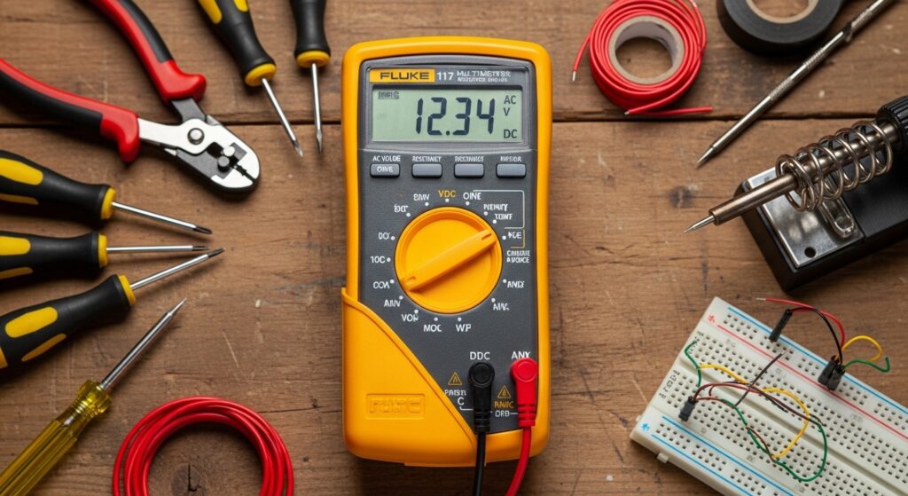
- Recommended: Fluke 117 or Klein Tools MM700
FAQs: Multimeter and Voltage Symbols
1. What is the AC voltage symbol on a multimeter?
The AC voltage symbol is a tilde (~) placed after or near the letter V — shown as V~, VAC, or ACV. On the meter dial, you may also see a sine wave graphic. This setting is used to measure alternating current voltage, like from wall outlets (120V in the US) or generators.
2. What is the symbol for DC voltage on a multimeter?
The DC voltage symbol is V—, where the dash and dotted line beneath represent direct, non-oscillating current. You may also see it labeled VDC or DCV. Use this setting for measuring batteries, car circuits, and solar panel outputs.
3. What does the ohms symbol (Ω) mean on a multimeter?
The Omega symbol (Ω) on a multimeter represents resistance measurement in ohms. When you set your meter to Ω, it sends a tiny test current through the component and measures how much that component resists the flow. Always use this setting only on de-energized circuits.
4. What is the continuity symbol on a multimeter?
The continuity symbol looks like a diode symbol (a triangle with a bar) or a series of arcs (like a sound wave). When enabled, the meter emits an audible beep when two points are electrically connected. This is used to verify wiring integrity, test fuses, and check switches without reading a number.
5. What do the symbols mA and μA mean on a multimeter?
- mA (milliamps) = 1/1,000 of an amp — used for measuring current in small electronic circuits
- μA (microamps) = 1/1,000,000 of an amp — used for ultra-sensitive current measurements in sensors or precision instruments
Both are found on the current (amperage) section of your multimeter dial, typically alongside the full-amp settings (A~ and A—).
Conclusion: You Now Speak Multimeter
Understanding the AC voltage symbol and every other symbol on your multimeter isn’t just about knowing the names — it’s about building confidence to actually use the tool safely and effectively.
To recap the essentials:
- ~ (tilde) = AC — for wall outlets, appliances, generators
- — (solid/dashed lines) = DC — for batteries, car circuits, solar
- Ω = Ohms — resistance measurement, on dead circuits only
- A with ~ or — = Current — always in series, always right jack
- mA, μA = Small current units — for low-power circuits
Whether you’re a homeowner checking if an outlet is live, a student learning electronics, or a DIY enthusiast troubleshooting a car battery, these symbols are your roadmap.
Ready to put your knowledge to work? Grab your multimeter, refer to this guide, and test away — safely.
Have a specific multimeter symbol you’re still confused about? Drop it in the comments — we’re happy to explain it.
